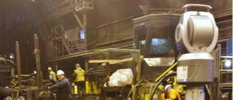
The application of surveying in the industrial sector is demanding increasingly precise measurements. This is because manufacturers, industrial designers and fabricators must achieve maximum production from their machinery to remain competitive in today’s marketplace. The accuracy of installations affects the quality of the product, speed of production, number of unsalable products, equipment life, and possibly the manufacturer’s equipment warranty.
If anything goes wrong, the plant will incur losses. This is of concern not just to the plant, but also to the installation contractor, as the surveyors installing the industrial equipment could be liable for those costs. Given this environment, it is crucial to utilize the latest technologies to meet today’s accuracy standards and ensure proper survey record documentation.
Still, the most common measurement tools currently utilized for industrial surveying are
optical instruments, often with a micrometer capable of readings within a few thousandths of an inch. To be fair, this technology is still effective in some cases. However, the optical instrument can supply only one measurement field – an X, Y, or Z reading. To obtain measurements in X and Z (elevation) in one instance, two different instruments (a transit and a level) would need to be set up. To obtain X, Y, and Z, technically three different instruments would need to be used, and keeping multiple instruments true and on the equipment lines and benchmarks would be a challenge during installation. Further, the observed X, Y and Z data would need to be compiled into one report. To achieve real-time results, calculations would need to be completed in the field on a calculator or computer program. Making 3D measurement comparisons in the field is very difficult without a CAD engine.
The use of
3D laser tracking equipment solves many of these problems. It is the future of high-precision measurement. 3D laser tracking provides accuracies that cannot be matched by optical survey equipment. In summary, the advantages of using 3D laser tracking include:
• 3D measurements within 0.002 inches.
• One tracker can provide X, Y, and Z measurements.
• A series of measurements can be made on an object to make a solid 3D CAD model.
• The tracker field software has a CAD engine and can model and analyze data for reports.
• All readings are documented and saved for final reports.
• High accuracy 3D project control networks can be created from random tracker positions.
• The tracker can be moved around the project and quickly reestablish its new position.
• The tracker is not set on true centerlines, which allows it to be set up away from the work area.
• The tracker head can be set up at any angle, even upside down.
• The tracker head can be mounted on brackets and attached to columns or bolted into concrete.
• The tracker software can adjust an entire survey network of control points in X, Y and Z positions.
• The software can make corrections for the temperature of the structure or equipment.
• All 3D point data can be downloaded into AutoCAD.
R.E. Warner is one of few firms with surveyors experienced in this technology as well as traditional methods, particularly for industrial applications.
Learn more or
contact us before your next equipment installation or alignment to discuss which approach is best for you.